Commercial LV Cabling Design
Standards-traceable 400 V cabling design for a three-tenancy commercial complex: maximum demand, cable selection, earthing, and fault verification to AS/NZS 3000 and AS/NZS 3008.1.1.
Read case study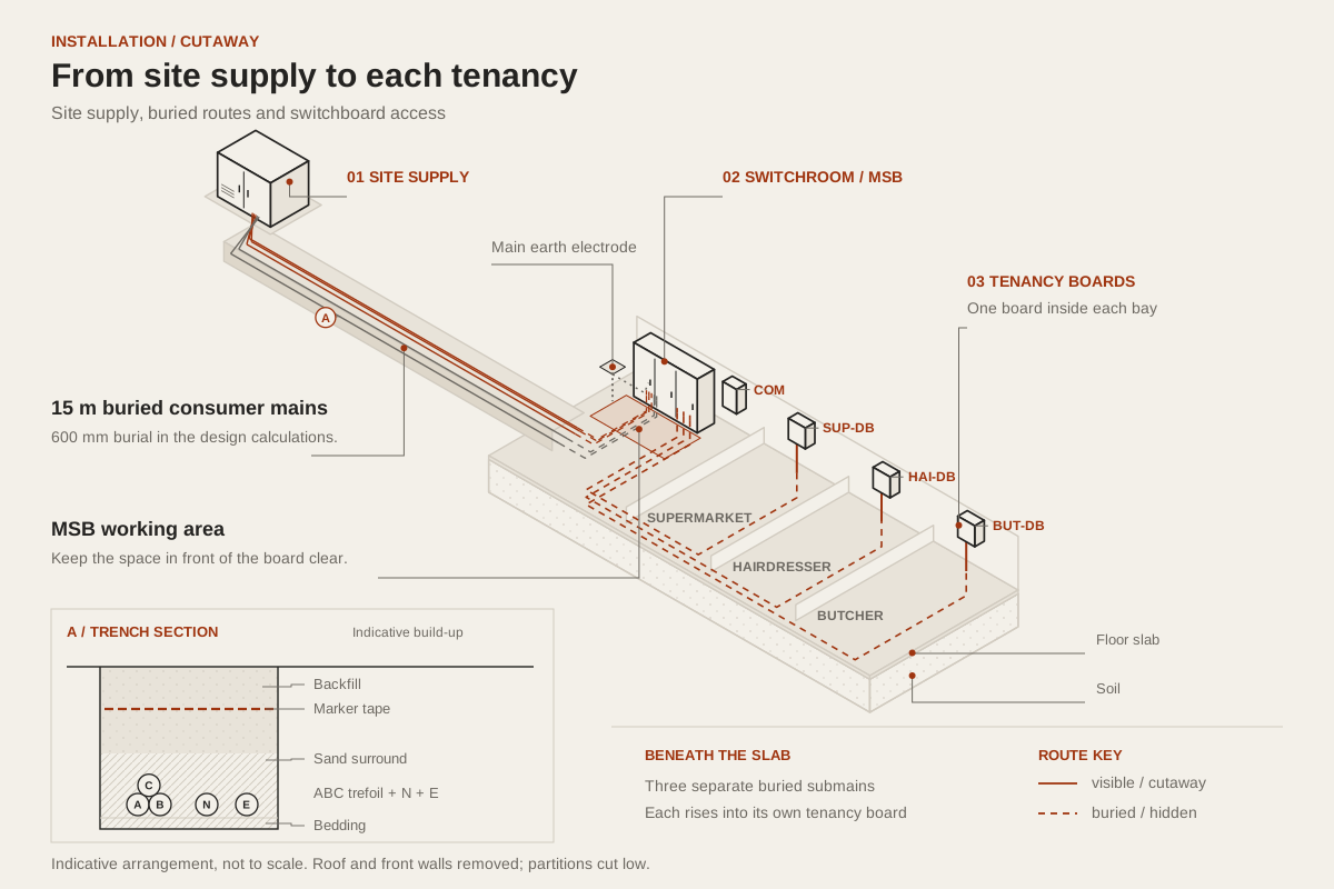
Electrical engineering student · Adelaide
Power systems and grid integration
I design to AS/NZS standards and publish the working, so please feel free to check it.
Supply · 500 kVA · 400 V 3-ph
Supply capacity S = 500 kVA · U₀ = 400 V · I_psc = 15 kA. Maximum demand: AS/NZS 3000:2018 Cl 2.2.2(a), Table C2 diversity; 85.6 kVA on the heaviest phase (Ib 123.6 A).
Consumer mains · 25 mm² X-90 Cu · Ib 123.6 A
I_b = S_demand / (√3 · U₀) with S_demand = 85.6 kVA; I_b ≤ I_n ≤ I_z with I_z from AS/NZS 3008.1.1:2025 Table 3.8 → Table 3.13 Col 19 (buried trefoil); corrections per Cl 3.4.3.
Voltage drop · ΔV 0.74 % vs 1 % brief limit
ΔV = √3 · I_b · L · R_c / 1000 ≤ 1 % of 400 V (project brief). AS/NZS 3000:2018 Cl 3.6.2 sets the 5 % installation limit.
Main switchboard · 125 A Type C · 8.0 kA fault
I_n = 125 A Type C; I_psc 8.0 kA ≤ 10 kA breaking capacity per Cl 2.5.4.2(a). EFLI: Cl 5.7.3, Table 8.1.
Supermarket submain · SUP-DB · 40 A · 6 mm² V-75
Submain: same chain; Table 3.8 → Table 3.12 Col 17 (one conduit). ΔV adds to the path budget against Cl 3.6.2's 5 %.
Hairdresser submain · HAI-DB · 25 A · 6 mm² V-75
Submain: same chain; Table 3.8 → Table 3.12 Col 17 (one conduit). ΔV adds to the path budget against Cl 3.6.2's 5 %.
Butcher submain · BUT-DB · 50 A · 10 mm² V-75
Submain: same chain; Table 3.8 → Table 3.12 Col 17 (one conduit). ΔV adds to the path budget against Cl 3.6.2's 5 %.
AS/NZS 3000 and 3008.1.1
Completed studies showing decisions, standards, calculations, and limitations.
Standards-traceable 400 V cabling design for a three-tenancy commercial complex: maximum demand, cable selection, earthing, and fault verification to AS/NZS 3000 and AS/NZS 3008.1.1.
Read case studyTechnical assessment for connecting a 1 MW solar plant to the SA Power Networks distribution grid: connection voltage, power-quality compliance, protection, and storage, with each conclusion argued against AS/NZS inverter standards and SAPN TS132/TS133.
Read case study
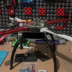
Indoor autonomy and staged verification.
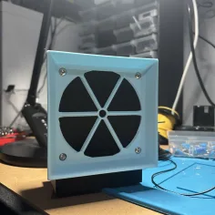
Builds, failures, and next iterations.